The ATOM Matrix includes a built-in 5x5 pixel RGB display, and the whole body acts as a button. This makes it great for acting as a digital 6-sided dice. In this post, I’ll show you how to do that using the standard M5Atom library for Arduino.
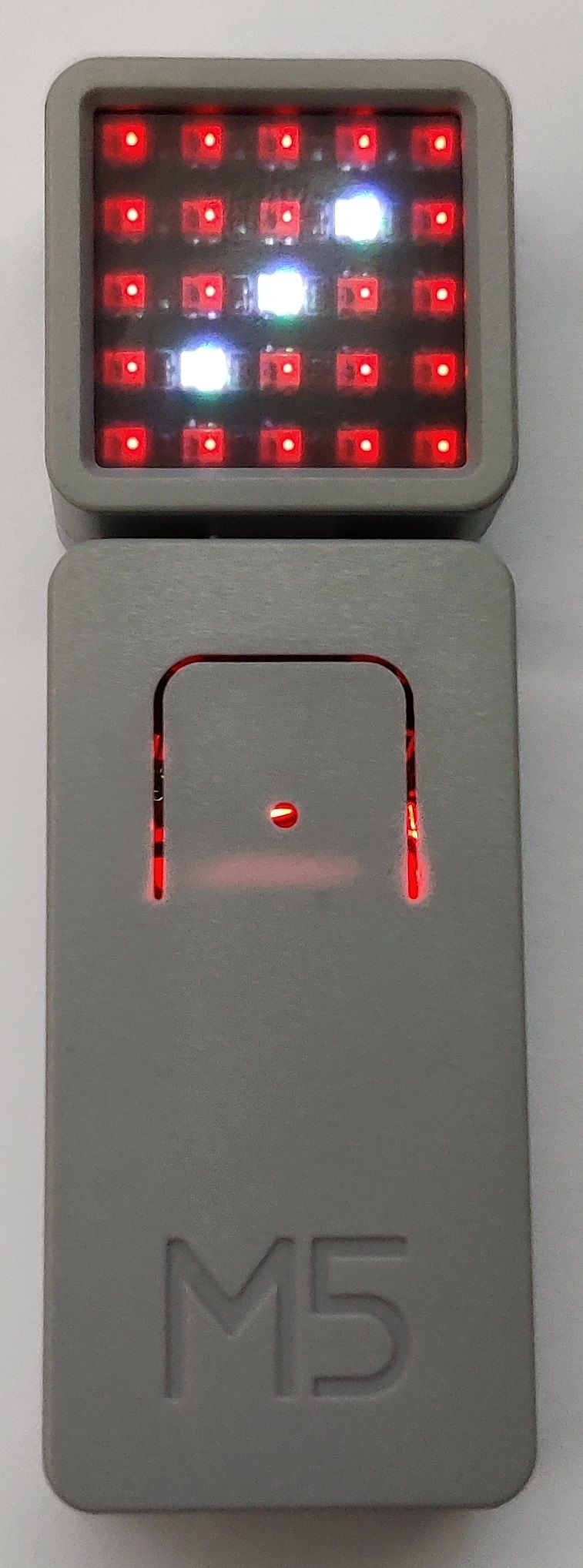 ATOM Matrix dice showing the number 3. The attachment on the bottom is the “TailBat” battery.
Requirements
If you haven’t done so already, you’ll need to install the Arduino IDE, and configure it for uploading sketches to the ATOM Matrix. You’ll also need to install the official M5Atom library. See my previous blog post for details on how to do this:
Source code
The full source code for this project is available on GitHub:
Feel free to dive straight in if you’re comfortable reading C++/Arduino code. Alternatively, keep reading this post if you’d prefer a step-by-step explanation of how it works.
Tutorial
Setup
Every Arduino sketch needs to have a function called setup(). It gets called once when the device is powered-on or reset, and is typically use to initialise a few things. Ours looks like this:
1
2
3
4
5
void setup()
{
  M5.begin(false, false, true);
  M5.dis.clear();
}
We’re doing two things here. First, we’re initialising the M5Atom library by calling M5.begin(). If you look at the source code for that function in the M5Atom class, you can get an idea of what its arguments are. They’re named:
SerialEnableI2CEnableDisplayEnable
We’re setting the first two arguments to false because we’re not using serial or I2C connections. However, we will be using the matrix display, which is why the third argument is true.
The second thing we’re doing in the setup function is clearing the matrix display (i.e. setting it to black). That’s done by calling M5.dis.clear(). This ensures nothing is left over on the display from the last time the sketch ran.
Loop
Every Arduino sketch also needs a loop() function. After setup() has finished, loop() gets called repeatedly until the device is powered-off or reset. Our loop function looks like this:
1
2
3
4
5
6
7
8
9
10
11
12
13
14
15
16
17
18
void loop()
{
  if (M5.Btn.wasPressed())
  {
    M5.dis.clear();
  }

  if (M5.Btn.wasReleased())
  {
    for (uint8_t i{ 0 }; i < 25; ++i)
      M5.dis.drawpix(i, g_backgroundColour);

    drawNumber(getRandomDiceRoll(), g_foregroundColour);
  }

  delay(25);
  M5.update();
}
There are a few things going on here, so we’ll break them down below.
Handle button press
When the user presses the button down, we want to immediately clear the display. This gives a useful visual clue that the button press has been detected. (We’ll display a new number later when they release the button.)
If you want, you can detect button presses on the Atom Matrix by directly querying GPIO pin 39. However, it’s more complicated than it sounds as you would have to “debounce” the signal and remember the state.
Luckily, the M5Atom library has a handy function which will do that all for us: M5.Btn.wasPressed(). It will return true if the button has been pressed down since the last time round the loop. If that happens, we clear the display by calling M5.dis.clear() again.
Handle button release
When the user releases the button, we want to generate and display a new random number. To do that, we use another handy function in the M5 library: M5.Btn.wasReleased(). As the name suggests, it returns true if the button has been released since the last loop.
When that happens, we do two things. First, we fill the matrix display with our chosen background colour. This involves a for loop which goes through each pixel (0 to 24). It sets it to our background colour using a function called M5.dis.drawpix().
The first argument in drawpix() is the index of the pixel we want to set, and the second is the colour we want to set it to. Index 0 is at the top-left, assuming the USB port is facing downwards. The pixels are then numbered left-to-right. When you reach the right-hand side, the numbering wraps around to the left-hand side of the next row down:
1
2
3
4
5
 0  1  2  3  5
 5  6  7  8  9
10 11 12 13 14
15 16 17 18 19
20 21 22 23 24
Note that the drawpix() function can also take X,Y coordinates instead of a single pixel index. You may find that easier to use, depending on your sketch.
The second thing we do when the button is released is to draw a new random number on the matrix using our chosen foreground colour. This actually involves two steps: picking a random number and then drawing it. However, we do it all in one line like this:
1
drawNumber(getRandomDiceRoll(), g_foregroundColour);
drawNumber() and getRandomDiceRoll() are custom functions in our sketch. I’ll explain those later on.
Update the M5Atom library
The last thing we do in the loop() function is to call M5.update(). It’s important to do this once on every loop. It will check for any changes in the button state, allowing functions like M5.Btn.wasPressed() and M5.Btn.wasReleased() to report presses correctly.
The delay() before we call update() isn’t strictly necessary. It just tells the microcontroller that we don’t need to do anything for a short time. There would be no point checking for button presses hundreds of times per second, after all, because humans probably can’t press it that quickly.
Microcontrollers like the ESP32 (which the ATOM Matrix is built on) can go into low-power mode during a delay. This is mainly helpful if you’re running on battery power. In practice though, the amount of energy saved is probably trivial compared to the amount needed to keep the matrix display illuminated.
Generate a random number
The first of our custom functions is called getRandomDiceRoll(). It just gets a random integer between 1 and 6 (inclusive). It’s implemented like this:
1
2
3
4
uint8_t getRandomDiceRoll()
{
  return (analogRead(32) % 6) + 1;
}
The first thing to note is that we’re not using the Arduino’s built-in random number function, which is called random(). That’s because it generates a predictable sequence of numbers, meaning you would get the same dice rolls every time.
Instead, we’re getting a random value by calling analogRead() to detect the voltage on pin 32. For this to work, there shouldn’t be anything connected to that pin; i.e. it should be “floating”. Nearby electrical noise will cause small random fluctuations in the pin’s voltage.
Hypothetically, any GPIO pin should work; the ESP32 can do analog-to-digital conversion on any of them. I chose pin 32 because it’s exposed on the Grove connector at the bottom of the ATOM Matrix. This means it’s hopefully more likely to pick up electrical noise from the environment.
The analogRead() function returns a number between 0 and 4096 on the ATOM Matrix. To bring this down to the range we want, we do a modulo operation, which is represented by the percentage symbol (%) in C/C++.
Our modulus is 6, which means it effectively divides the analog reading by 6, then gives us the remainder. This results in a value between 0 and 5 inclusive, so we just add 1 to get the desired range of 1 to 6.
At this stage, it’s important to note that the voltage fluctuations on a floating pin are fairly small, and strictly speaking they aren’t truly random. However, they are big enough and random enough for a simple dice roll. You wouldn’t want to use this technique to generate much larger random numbers, or for important applications such as cryptography.
Draw a number
Our second custom function is a very important one: it’s called drawNumber() and it displays our random number on the matrix. It’s implemented like this:
1
2
3
4
5
6
7
8
9
10
11
12
13
14
15
16
17
18
19
20
21
22
23
24
25
26
27
28
29
30
31
32
33
34
35
36
37
38
39
40
41
42
43
44
void drawNumber(const uint8_t number, const CRGB colour)
{
  switch (number)
  {
  case 1:
    M5.dis.drawpix(12, colour);
    break;

  case 2:
    M5.dis.drawpix(8, colour);
    M5.dis.drawpix(16, colour);
    break;

  case 3:
    M5.dis.drawpix(8, colour);
    M5.dis.drawpix(12, colour);
    M5.dis.drawpix(16, colour);
    break;

  case 4:
    M5.dis.drawpix(6, colour);
    M5.dis.drawpix(8, colour);
    M5.dis.drawpix(16, colour);
    M5.dis.drawpix(18, colour);
    break;

  case 5:
    M5.dis.drawpix(6, colour);
    M5.dis.drawpix(8, colour);
    M5.dis.drawpix(12, colour);
    M5.dis.drawpix(16, colour);
    M5.dis.drawpix(18, colour);
    break;

  case 6:
    M5.dis.drawpix(6, colour);
    M5.dis.drawpix(8, colour);
    M5.dis.drawpix(11, colour);
    M5.dis.drawpix(13, colour);
    M5.dis.drawpix(16, colour);
    M5.dis.drawpix(18, colour);
    break;
  }
}
It takes two parameters: the number you want to draw, and the colour you want to use. The body of the function is quite simple. It draws the dots by setting individual pixels to our foreground colour, using the drawpix() function we saw earlier. There’s a separate block of code for each number, and it uses a switch statement to decide which block of code to run.
For example, here’s the block for the number 4:
1
2
3
4
5
6
    case 4:
        M5.dis.drawpix(6, colour);
        M5.dis.drawpix(8, colour);
        M5.dis.drawpix(16, colour);
        M5.dis.drawpix(18, colour);
        break;
That sets pixels 6, 8, 16, and 18 to the foreground colour, which makes it look like the typical arrangement of 4 dots on traditional 6-sided dice. All the other pixels continue showing the background colour.
Customising the colours
It’s easy to change the foreground and background colours if you like. Look for variables called g_foregroundColour and g_backgroundColour declared near the top of the code:
1
2
3
const CRGB g_foregroundColour{ 0xffffff };

const CRGB g_backgroundColour{ 0x003300 };
The colours are set using hexadecimal numbers, such as 0xffffff. It’s similar to how hex codes are used for colours in other areas, such as web-development. However, the red and green components are swapped round compared to normal. Also, as we’re working in C++, you need to start a hex number with 0x instead of #.
The default colours are white dots on a dark red background. When I think of traditional dice, those are the colours I think of first. Here are some other colour values you might want to try:
- Black:
0x000000 - White:
0xffffff(bright),0x888888(dark) - Red:
0x00ff00(bright),0x003300(dark) - Green:
0xff0000(bright),0x330000(dark) - Blue:
0x0000ff(bright),0x000033(dark) - Pink:
0x00ffff(bright),0x003333(dark) - Yellow:
0xffff00(bright),0x333300(dark) - Cyan:
0xff00ff(bright),0x330033(dark)
How to load the sketch
- Download the complete program from here.
- Open the file in the Arduino IDE.
- Connect your ATOM Matrix to your computer via USB.
- Select the appropriate board / port for upload.
- Click the Upload button and wait for it to finish.
When it’s finished, the matrix display will be initially blank. Press and release the matrix button to see a random dice roll. Each time you press it, you will get a new random number.
You can clear the display by pressing the reset button on the side of the ATOM Matrix.
Next steps
There are 25 pixels to play with on the ATOM Matrix, so you aren’t limited to a 6-sided dice. You could add more arrangements of dots, or you could make it draw numerical digits instead. You could even draw some letters, such as H (heads) and T (tails) for a digital coin toss.
Other fun features you could add include:
- Show a “rolling” animation on the matrix when a new random number is being generated.
- Use the on-board accelerometer to detect when the device is shaken, and use that as a trigger to “roll” the dice.
- Allow the user to select different dice or colour schemes by long-pressing the button.