A serial-to-parallel shift register (or SIPO: Serial In Parallel Out) lets you take a series of signals on one output and split them up into several separate outputs in parallel. For example, if you don’t have enough GPIO pins on your Raspberry Pi, Arduino, or other computer/microcontroller, you may be able to use a shift register to add more.
In this post, I’ll be looking at the 74HC595, which is an 8-bit SIPO integrated circuit; i.e. it gives you 8 outputs. The advantage of this chip over some dedicated port expanders is that it doesn’t require a complex protocol like I2C or SPI, and it doesn’t need a particular clock speed. That means you can control it with pretty much any digital output channels, and it’s very easy to write simple software to communicate with it.
What does a shift register do?
In general, a shift register is a memory buffer which you write to and/or read from sequentially, depending on the application.
In the case of a serial-to-parallel shift register, you push data onto the beginning of the register, one bit at a time. Each time you do that, the existing data shuffles along to make room. Typically, you keep going until you’ve filled up the register, and then trigger a transfer.
The transfer copies all the data in the shift register over into a separate storage register. This will usually be connected to a series of outputs which all get updated simultaneously. This allows the outputs to hold the current values steady while you re-fill the shift register with the next block of data. You then trigger another transfer to update the outputs, and so on.
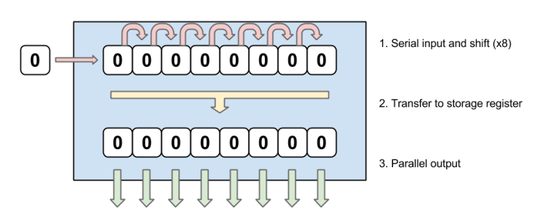 Functional overview of a serial-to-parallel shift register
This makes it great for expanding outputs from something like a Raspberry Pi or Arduino. You use 3 of your device’s output pins to give data in serial to the register. It gets converted to parallel, letting you treat it as though you’ve got 8 or 16 (or more) individual output pins. It’s inevitably slower than having actual output pins, but it is effective for many purposes.
One of the great things about these components is that you can ‘daisy-chain’ them together. When you push a bit on to the shift register, the last bit has nowhere to go when everything else shuffles along. This means it usually just gets discarded. However, you can actually redirect it to the input for a second shift register, effectively doubling the output capacity. As long as you’ve got enough power, there’s nothing stopping you from daisy-chaining more. Just be aware that longer chains take more time to update.
How do you control the shift register?
The 74HC595 is controlled by a data input pin (DS), a shift clock pin (SHCP or SRCLK), and a storage clock pin (STCP or RCLK). They are all active high. In the case of the clock pins, you’ll need to make sure they’re pulled properly low (not floating) in between clock pulses, otherwise you’ll get odd behaviour.
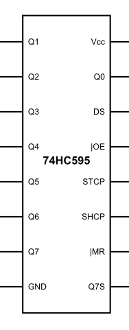 Pin-out diagram of a 74HC595 shift register
When you want to move data onto the register, first set the data input pin (DS) high or low, representing the bit you want to send (i.e. 1 or 0). After that, briefly set the shift clock pin (SHCP) high, and then bring it back to low. Repeat this process as many times as you need to get data where you want it on the register (typically 8 times to fill a single register).
When you want to copy data to the output register, briefly pulse the storage clock pin high, then bring it back to low. (You’ll need to pull the Output Enable (OE) low as well, although as noted below I keep it held low at all times.)
And that’s it! The device is capable of fairly high speeds, so you can whizz quite a bit of data through. Bear in mind that the outputs aren’t capable of handling much load though, so remember to use transistors or similar if you want to power other devices directly.
Pin connections
Be careful of voltages when connecting the shift register to a device. The 74HC595 can work with a range of voltages, including 3.3v for Raspberry Pi, and 5v for most Arduinos. However, check your datasheets! In particular, watch out for the 74HCT595 (notice the “T” in there). It will probably not operate properly at 3.3v.
The supply (Vcc) and ground (GND) pins are hopefully obvious — hook those up to your power supply and ground lines.
The input and clock pins I mentioned above are obviously very important too. You’ll want to connect each of these to a digital output on your device. It would be wise to enable (or manually attach) weak pull-down resistors on these pins too, so that you don’t end up with unpredictable behaviour.
The Master Reset (MR) pin should be held high most of the time (e.g. by bridging it to Vcc). If this pin is pulled low then it will reset the entire shift register, basically filling it with 0’s. You can control this line from your device as well if you want, or connect it to a central reset circuit.
I usually prefer to hold the Output Enable (OE) pin low, e.g. by bridging it to GND. This keeps the storage register connected to the output pins at all times. If you let it go high then the output pins will float. This could have an odd effect on whatever is connected to the outputs, unless you add circuitry to detect it.
If you’re only using a single shift register, you can leave the serial output pin unconnected (usually labelled Q7S, or sometimes Q7′).
Finally, hook up the output pins to whatever components you want to control (Q0 to Q7).
Linking multiple shift registers (daisy-chaining)
Each time you shift a new bit onto the register, the bit in the last position effectively drops off the end. However, before it disappears into oblivion, it sits on the serial output (pin Q7S or Q7′) for one shift cycle.
If you connect this pin to the serial input pin (DS) of a second register, you can increase your shift capacity, allowing them to work together like a 16-bit shift register. If you connect the serial output (Q7S) on your second register to the serial input of a third register, they’ll act like 24-bit, and so on.
All the other pins on your second/third/etc. registers are connected the same way as they are on your first. Most importantly, the clock pins (shift and storage) are connected to the same outputs on your device. This is vital because they must all shift/store at exactly the same time.
In practice, there are limitations on how many shift registers you can link together like this. The problem you’re likely to encounter first is power. You’re connecting the same device pins to the clock inputs on multiple chips, which means you’re dividing the current between them. If it’s divided too much then it will stop working.
The number of registers you can drive depends on how much power your device can supply on its outputs. There are many possible workarounds though, such as using buffers.
The other potential limitation is speed. As you increase the number of registers, you increase the number of shifts you need to do to get the data all the way through to the last output. That means each update will be slower. With that said, the shifts are usually very fast, so the chances are that you won’t have a problem on small-to-medium projects.
Example project: numeric display
I connected a pair of daisy-chained shift registers to my Raspberry Pi. That allowed me to turn 3 GPIO pins into 14 separate outputs, which I used to control a 4-digit numeric display. (The last 2 outputs on the shift registers weren’t needed.)
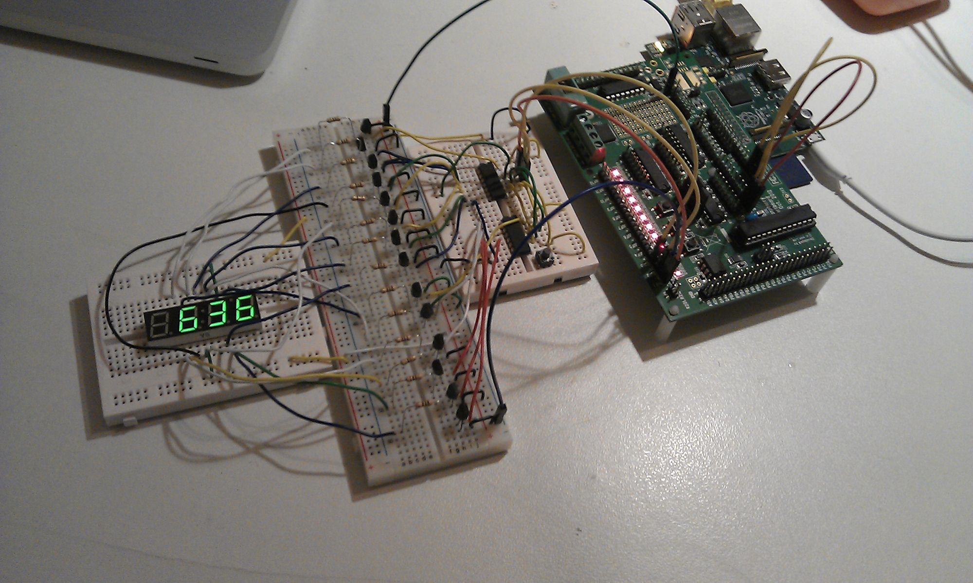 Example project using a shift register to run a numeric display
From right to left, the major components are:
- An old Raspberry Pi.
- Gertboard (handy expansion for tinkering with the Pi).
- Small breadboard with 2 shift registers.
- Medium breadboard with lots of transistors and resistors.
- Small breadboard with the numeric display.
This project presented a bit of a challenge. The first difficulty was that the shift registers couldn’t source/sink enough current to drive it directly, hence the unholy number of transistors (I didn’t have a transistor package handy!).
The second difficulty was that you can’t show multiple digits at the same time on this kind of display. There’s a common anode for each digit, and then a common cathode for each type of segment across all digits. That means you have to flash each digit quickly, one-at-a-time, similar to how you’d use a PWM to control the brightness of an LED. If you do that fast enough, it gives the impression of a steady display. That required a reasonably high throughput of data in the shift registers.
You can take a look at the rough circuit diagram below. It may not be entirely accurate though (especially the resistor values). Please note that I was just tinkering with a few components I had lying around. This is not the best way to build a circuit like this, so I absolutely cannot guarantee the safety of your components if you copy it!
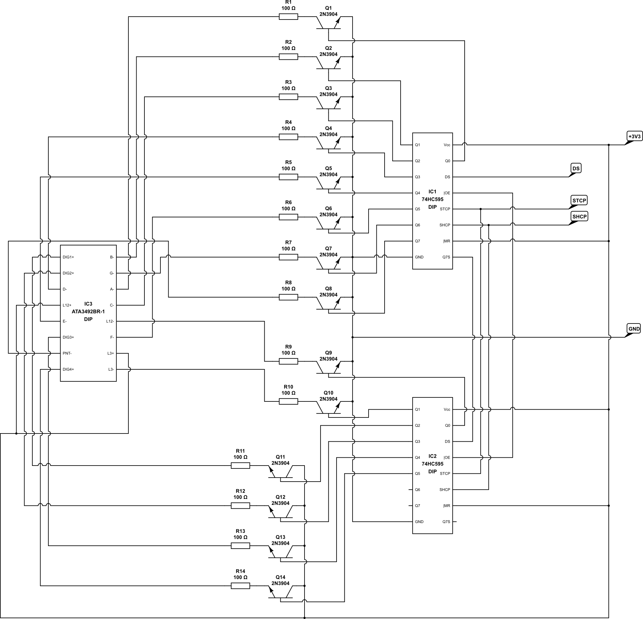 Example circuit using a serial-to-parallel shift register
IC1 and IC2 are the shift registers, and IC3 is the numeric display. Connections DS, STCP, and SHCP go to GPIO pins on the Raspberry Pi.
In reality, this is a totally impractical way to attempt this kind of project, and you’d be far better off investing a little extra in a dedicated IC to control it for you. I just did it this way because it was a fun little experiment.
Conclusion
The serial-to-parallel shift register is a simple but effective way to expand your available outputs. You could use it to control lights or motors, or to pass information to other devices which require parallel data.
It’s worth noting that there are plenty of “port expanders” and similar components which do something similar. However, they often require the use of I2C or SPI. They have the advantage that you can control several different components on the same bus. They can be a good option if your device supports the relevant protocol and has suitable outputs available.
The beauty of the shift register though is its simplicity. Pretty much any device can be made to talk to them, and the programming is simple enough to be quite fun if you’re a hobbyist.